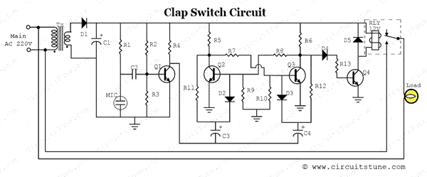
This is a simple clap switch circuit diagram project. If you are a beginner electronics learner, and love to do new project experiment then this is a great circuit for you. This circuit can on/off a 220V electronic device like fan, lamp by the sound of clap.
The basic principle applied in this circuit:
A small microphone (MIC) detects the clap sound and converts into electrical signal. Which is amplified by Q1 (here Q1 used as a common emitter amplifier). Amplified signal goes into the Bistable Multivibrator section made by two transistors Q2 and Q3.
When we apply a trigger to the Bistable Multivibrator circuit with a clap sound then, if Q2 is on, Q3 gets switched off. Thus, the circuit remains stable in a single state continuously. At the moment if we trigger with another clap sound the two states will flip-flop with Q2 switched off and Q3 switched on. The circuit will remain stable continuously until we apply the next trigger.
Relay gets triggered from the output of current-amplifier (Q4) which is used to amplify the flip-flop signal. Relay is kind of electromagnetic switch, which is used to controlling other high voltage (AC) electrical appliance (Load in our circuit) with this low voltage (DC) clap switch.
Circuit diagram of clap switch
Watch The Video Of Clap Switch Circuit Diagram Project
Circuit Description
As shown in the circuit a very few number of parts is used including relay, transformer, condenser microphone, few transistor, a lamp etc. Lamp is used as a testing device; here another device could be use like fan, calling bell, radio etc.
The basic principle applied in this circuit:
“Clap sound is being converted into electrical signal and a relay gets triggered from it and controls the load.”
A small microphone (MIC) detects the clap sound and converts into electrical signal. Which is amplified by Q1 (here Q1 used as a common emitter amplifier). Amplified signal goes into the Bistable Multivibrator section made by two transistors Q2 and Q3.
When we apply a trigger to the Bistable Multivibrator circuit with a clap sound then, if Q2 is on, Q3 gets switched off. Thus, the circuit remains stable in a single state continuously. At the moment if we trigger with another clap sound the two states will flip-flop with Q2 switched off and Q3 switched on. The circuit will remain stable continuously until we apply the next trigger.
Relay gets triggered from the output of current-amplifier (Q4) which is used to amplify the flip-flop signal. Relay is kind of electromagnetic switch, which is used to controlling other high voltage (AC) electrical appliance (Load in our circuit) with this low voltage (DC) clap switch.
Part List:
R1 = 15KΩ Resistor
R2, R11, R12 = 2.2MΩ Resistor
R3 = 270KΩ, R4 = 3.3KΩ Resistor
R5, R6 = 1.5KΩ Resistor
R13 = 2.2KΩ Resistor
R3 = 270KΩ Resistor
R4 = 3.3KΩ Resistor
R7, R8 = 10KΩ Resistor
R9, R10 = 27KΩ Resistor
C1 = 1000µf/16v Capacitor
C2 = .01µf Capacitor
C3, C4 = .047µf Capacitor
Q1, Q2, Q3 = BC548 Transistor
Q4 = BC368 Transistor
D2, D3, D4 = IN 4148 Diode
D1, D5 = IN 4007 Diode
MIC = Condenser Microphone
RLY = 12V Relay
Load = AC 220V Bulb or Fan
Tx = 12v/0.5A Transformer
12V/5-Pin Relay Pinout
BC548 and BC368 Transistor Pinout

Reference: Bistable Multivibrator [wikipedia]


can i use another transistor instead of bc 547
ReplyDeleteYes you can use other equivalent transistor of bc 548
Deletewe can use 9 v transformer
ReplyDelete